A multi-discipline Outsourcing Company
offering wide range of Engineering Design
and CAD / BIM Drafting Services
offering wide range of Engineering Design
and CAD / BIM Drafting Services


Menu


 Our work is dedicated
to prosperity of our Clients Our Mission...
On-Time Design Deliveries,
High Quality Designs, 100% Client Satisfaction. Happy Clients
in more than 10 Countries.
Projects
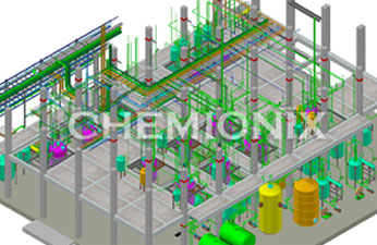
Engineering Design Projects:
A broad portfolio of engineering design project
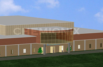
Architechure Design Projects:
A broad portfolio of archieture project
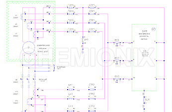
Electrical Design Projects:
A broad portfolio of electrical design project
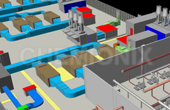
Mechanical Design Projects:
A broad portfolio of mechanical project

CAD Conversion Projects:
A broad portfolio of CAD conversion project